Set the 3-D Viewing Space
3-D scenes can be rendered in two ways:
• Orthographic projections place the elements in a box, where coordinates are not changed to accommodate the perspective of the viewer.
• Perspective projections modify the display to simulate the position of the elements in relation to the position of the viewer.
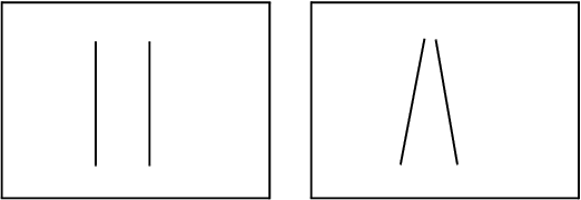
For example, two parallel lines (like railroad tracks) stay parallel in orthographic projections, but seem to connect at a distance in perspective projections.
Figure 13.4 Parallel Lines in an Orthographic Projection (left) and a Perspective Projection (right)
As another example, imagine looking at a tube edge-on (like a telescope). In an orthographic projection, the tube would appear as a thin circle. In a perspective projection, the circle would have a thickness; the hole at the far end of the tube would appear smaller than the close hole, and the interior of the tube is visible.
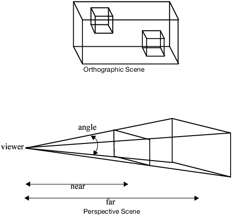
Therefore, the viewable space of an orthographic projection is a rectangular shape. That of a perspective projection is the frustum of a pyramid (that is, a pyramid whose top has been sliced off).
Figure 13.5 Comparing Projections
In general, perspective projections give a more realistic view of the world, since it mimics the way an eye or a camera sees. Orthographic projections are important when it is essential to preserve dimensions, such as an architectural CAD program.
Set Up a Perspective Scene
To set up a perspective scene in JSL, send the Perspective message to a display list.
Perspective (angle, near, far)
where angle is the viewing angle, near is the distance to the near plane, and far is the distance to the far plane, as illustrated in the drawing above. A couple of things need to be remembered when defining the viewing space.
• Items outside the viewing space (for example, closer than the near plane or farther than the far plane) are not drawn. They are clipped off.
• The ratio of far to near needs to be small. This enables the rendering engine to effectively determine which items should be drawn “on top of” other items, simulating closeness of items. The near argument must be greater than zero.
The “Hello World” example contains the line
scene << Perspective( 45, 3, 7 ); // define the camera
This defines a 45-degree viewing angle, with a near plane 3 units from the viewer and a far plane 7 units from the viewer.
The viewing angle functions in the same way as a wide angle or telephoto lens on a camera. Small viewing angles zoom into a drawing; wide angles zoom out. In other words, a small viewing angle maps the screen space onto a small portion of the scene, resulting in apparently larger scene elements. A large viewing angle maps the screen space onto a large portion of the scene, resulting in apparently small screen elements. The size of scene elements can therefore be manipulated using the angle argument of the Perspective function. The picture here shows the hello world script with perspective angles of 45 and 90 degrees.
Figure 13.6 Changing the Perspective
As an alternative to the Perspective message, you can define the actual viewing frustum with the Frustum message.
Frustum(left, right, bottom, top, near, far);
The frustum's viewing volume is defined by (left, bottom, near) and (right, top, near), which specify the (x, y, z) coordinates of the lower left and upper right corners of the near clipping plane; near and far give the distances from the viewpoint to the near and far clipping planes.
Set up an Orthographic Scene
In JSL, orthographic scenes are specified similarly to perspective scenes. Issue the following expression:
Ortho(left, right, bottom, top, near, far)
which specifies the four corners of the near plane, the distance to the near plane, and the distance to the far plane.
If you are dealing with a simple 2-D environment, you can set up a two-dimensional orthographic scene with the following expression:
Ortho2D (left, right, bottom, top)
which specifies the corners of the two-dimensional view.


