Control the Appearance of Primitives
JSL has several commands that let you tailor-make the appearance of primitive drawing objects. You can also specify the widths of lines and their stippling pattern (that is, whether they are dashed, dotted, and so on.)
Size and Width
To set the point size of rendered objects, use the Point Size command.
Point Size( n )
where n is the number of pixels. Note that this might not be the actual number of pixels rendered, depending on other settings such as anti-aliasing and your hardware configuration.
Set the line width using the Line Width command
Line Width( n )
where n is the number of pixels. The argument n must be larger than zero and is, by default, one.
Stippled Pattern
To make stippled lines, use the Line Stipple function.
Line Stipple( factor, pattern )
Factor is a stretching factor. Pattern is a 16-bit integer that turns pixels on or off. Use Enable(LINE_STIPPLE) to turn the effect on.
To construct a line stippling pattern, write a 16-bit binary number that represents the stippling pattern that you desire. Note that the pattern should read from right to left, so your representation might seem backward to the way it is rendered. Convert the binary number to an integer and use this as the pattern argument.
For example, imagine you want the dotted line pattern 0000000011111111. This is equal to 255 in decimal notation, so use the expression Line Stipple(1, 255).
The factor argument expands each binary digit to two digits. In the example above, Line Stipple(2, 255) would result in 00000000000000001111111111111111.
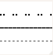
For example, the following script draws three lines, each of different widths (the Line Width messages) and stippling patterns.
scene = Scene Box( 200, 200 ); // make a scene box...holds an OpenGL scene
New Window( "Stipples", scene ); // put the scene in a window
scene << Ortho( -2, 2, -2, 2, -1, 1 );
scene << Color( 0, 0, 0 ); // set the RGB color of the text
scene << Enable( LINE_STIPPLE );
scene << Line Width( 2 );
scene << Line Stipple( 1, 255 );
scene << Begin( LINES );
scene << Vertex( -2, -1, 0 );
scene << Vertex( 2, -1, 0 );
scene << End();
scene << Line Width( 4 );
scene << Line Stipple( 1, 32767 );
scene << Begin( LINES );
scene << Vertex( -2, 0, 0 );
scene << Vertex( 2, 0, 0 );
scene << End();
scene << Line Width( 6 );
scene << Line Stipple( 3, 51 );
scene << Begin( LINES );
scene << Vertex( -2, 1, 0 );
scene << Vertex( 2, 1, 0 );
scene << End();
scene << Update;
Figure 13.11 Stipples
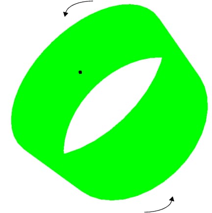
Note: Stipple patterns “crawl” on rotating models because they are in screen pixels, not model units. Lines in the model change length on the screen even though nothing changes in model units.
Fill Pattern
Polygons are rendered with both a front and a back, and the drawing mode of each side is customizable. This enables the user to see the difference between the back and front of the polygon.
To set the drawing mode of a polygon, use the Polygon Mode function.
Polygon Mode( face, mode )
where face can be FRONT, BACK, or FRONT_AND_BACK, and mode can be POINT, LINE, or FILL.
Figure 13.12 Points, Line, and Fill Modes
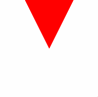
For example, the following script creates a display list that defines a triangle. This display list is used three times in conjunction with Translate, Rotate, and Color commands to draw triangles in three positions. In addition, the Polygon Mode command changes the drawing mode of each triangle. Note there is no explicit call to the FILL mode, since it is the default.
The following table dissects the script, showing how the Translate and Rotate commands accumulate to manipulate a single display list.
Code from above script | comments |
|---|---|
shape = Scene Display List(); | Creates a display list |
shape << Begin( TRIANGLES ); shape << Vertex( 0, 0, 0 ); shape << Vertex( -1, 2, 0 ); shape << Vertex( 1, 2, 0 ); shape << End(); | Creates a display list named shape that holds vertices for the triangles. All the z vertices are zero since this is a two dimensional scene |
scene = Scene Box( 200, 200 ); New Window( "Fill Modes", scene ); scene << Ortho2d( -2, 2, -2, 2 ); | Put the scene in a display box, and create a new window. |
scene << Color(1,0,0); scene << Call List( shape );
// update the scene to see the triangle scene << Update;
| Draw the first triangle in red.
|
scene << Rotate ( 90, 0, 0, 1 ); scene << Translate ( -0.5, 0, 0 ); scene << Color( 0, 0.5, 0.5 ); scene << Polygon Mode( FRONT_AND_BACK, LINE ); scene << Call List( shape );
// update the scene to see the triangle scene << Update;
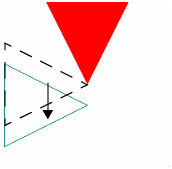
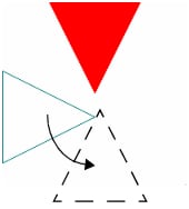
| Draw the second triangle in teal. Note that we first rotate the triangle.
And then translate it.
|
scene << Rotate( 90, 0, 0, 1 ); scene << Translate( -0.5, -1, 0 ); scene << Color( 0, 0, 0 );
// large points so that they are visible scene << Point Size( 5 ); scene << Polygon Mode( FRONT_AND_BACK, POINT ); scene << Call List( shape );
// update the scene to see the triangle scene << Update; | Draw the third triangle as black points. First rotate.
And then translate to get the final picture.
|
Some developers use the fill mode in concert with the line mode to draw a filled polygon with a differently colored border. However, due to the way the figures are rendered, they sometimes do not line up correctly. The Polygon Offset function is used to correct for this so-called “stitching” problem.
Polygon Offset (factor, units)
To enable offsetting, use Enable(POLYGON_OFFSET_FILL), Enable(POLYGON_OFFSET_LINE), or Enable(POLYGON_OFFSET_POINT), depending on the desired mode. The actual offset values are calculated as m*(factor)+r*(units). m is the maximum depth slope of the polygon and r is the smallest value guaranteed to produce a resolvable difference in window coordinate depth values. Start with Polygon Offset(1,1) if you need this.
An example of Polygon Offset is in the Surface Plot platform, when a surface and a mesh are displayed on top of each other, or a surface and contours displayed on top of each other. In either case, the surface would interfere with the lines if the lines were not moved closer or the surface moved farther from the viewer.
